English
 Afrikaans
 Albanian
 Amharic
 Arabic
 Armenian
 Azerbaijani
 Basque
 Belarusian
 Bengali
 Bosnian
 Bulgarian
 Catalan
 Cebuano
 Chichewa
 Chinese (Simplified)
 Chinese (Traditional)
 Corsican
 Croatian
 Czech
Czech Danish
 Dutch
Dutch Esperanto
 Estonian
 Filipino
 Finnish
 French
 Frisian
 Galician
 Georgian
 German
 Greek
Greek Gujarati
 Haitian Creole
 Hausa
Hausa Hawaiian
 Hebrew
 Hindi
Hindi Hmong
Hmong Hungarian
 Icelandic
 Igbo
Igbo Indonesian
 Irish
Irish Italian
 Japanese
 Javanese
 Kannada
 Kazakh
 Khmer
Khmer Korean
 Kurdish (Kurmanji)
 Kyrgyz
 Lao
Lao Latin
Latin Latvian
 Lithuanian
 Luxembourgish
 Macedonian
 Malagasy
 Malay
Malay Malayalam
 Maltese
 Maori
Maori Marathi
 Mongolian
 Myanmar (Burmese)
 Nepali
 Norwegian
 Pashto
 Persian
 Polish
 Portuguese
 Punjabi
 Romanian
 Russian
 Samoan
 Scottish Gaelic
 Serbian
 Sesotho
 Shona
Shona Sindhi
 Sinhala
 Slovak
 Slovenian
 Somali
 Spanish
 Sundanese
 Swahili
 Swedish
 Tajik
Tajik Tamil
Tamil Telugu
 Thai
Thai Turkish
 Ukrainian
 Urdu
Urdu Uzbek
Uzbek Vietnamese
 Welsh
Welsh Xhosa
Xhosa Yiddish
 Yoruba
 Zulu
Zulu


An Infrared Multilayer Coating must do two jobs at once: transmit useful infrared energy with limited loss and reject unwanted wavelengths before they reach the detector. These goals conflict. More layers may strengthen blocking, but they also add interfaces, thickness sensitivity, absorption risk, and passband ripple.
BoDian Optical develops optical thin-film components across ultraviolet, visible, and infrared bands. Its infrared work includes narrowband, broadband, long-pass, short-pass, and anti-reflection filters, together with custom coating and spectral testing. Buyers should focus on whether the supplier can connect the target spectrum with substrate selection, deposition control, and final inspection.

Why Is It Difficult to Combine High Transmittance with Deep Rejection?
A deep rejection infrared filter is not created by adding layers without limit. The substrate, detector response, incidence angle, and temperature range must be treated as one system.
Refractive-Index Contrast Defines the Rejection Zone
Alternating high- and low-index layers create a high-reflectance region through interference. A larger refractive-index contrast generally produces a wider rejection zone and stronger blocking with fewer periods. The material pair must still remain transparent in the required passband. A material that absorbs at the operating wavelength will still reduce the useful signal.
Absorption and Interface Reflection Reduce Passband Energy
Transmission loss does not come from one source. Part may be reflected at the substrate surface, part may be absorbed by the substrate, and part may be lost inside the deposited films. Infrared substrates such as germanium, silicon, sapphire, calcium fluoride, zinc sulfide, and zinc selenide offer different transmission windows and mechanical properties.
Thermal behavior must also be considered. During heating and cooling, differences in the coefficient of thermal expansion between the substrate and coating materials add mechanical strain to the residual stress already present in the stack. Repeated expansion and contraction may produce tensile or compressive stress, spectral drift, fine cracking, or delamination, especially near coating edges and surface defects. Material selection should therefore consider thermal compatibility as well as refractive index and infrared transparency. Deposition temperature, total coating thickness, layer sequence, edge condition, and post-coating thermal cycling all affect whether the design remains stable in service.
Sideband Suppression Creates a Transmission Trade-Off
A narrow passband can be accompanied by unwanted higher-order transmission peaks. Extra blocking sections may suppress them, but poor matching between those sections can lower peak transmission or create ripple. A good infrared multilayer coating balances the passband, sideband control, and detector sensitivity.
Which Design Choices Determine Infrared Multilayer Coating Performance?
For an infrared multilayer coating, the design must be manufacturable. A less aggressive structure with better tolerance may outperform a sensitive theoretical curve.
Cavity Structures and Matching Layers Control Ripple
Narrowband filters use reflector stacks around one or more cavity layers. The cavity defines the transmitted band, while the surrounding stacks create rejection. Matching layers at the incident side and substrate side reduce admittance mismatch and passband ripple. Computer refinement can adjust thicknesses, but it cannot make an unstable layer sequence reliable.
Substrate Selection Must Follow the Infrared Window
The substrate affects transmission, reflection, thermal behavior, coating adhesion, and final component cost. Buyers should specify wavelength range, thickness, surface quality, clear aperture, shape, and mounting method. A high transmittance infrared coating on a substrate with unsuitable absorption will still underperform.
Angle of Incidence and Temperature Shift the Spectrum
Interference filters shift toward shorter wavelengths as the incidence angle increases. At larger angles, s- and p-polarized light may separate, changing the apparent passband. Temperature can also move the peak because film thickness and refractive index change. The RFQ should state angle, beam cone, polarization, and operating temperature rather than rely only on normal-incidence data.
How Does Process Control Keep Multilayer Coatings within Tolerance?
In production, an infrared multilayer coating depends on deposition rate, chamber distribution, substrate cleaning, material stability, and monitoring logic.
Direct Optical Monitoring Supports Error Compensation
Direct optical monitoring measures the growing stack rather than treating every layer as an isolated film. In narrowband work, an over-thick layer may be followed by a thinner compensating layer, helping maintain the controlled wavelength. Compensation does not remove all error. Bandwidth may broaden and peak transmission may fall if reflector sections become unbalanced.
Quartz-Crystal and Time Monitoring Stabilize Deposition
Quartz-crystal monitoring measures deposited mass and needs separate calibration for each material. Typical mass-thickness accuracy may be around 2%, which can suit simpler coatings. Narrow multiple-cavity filters can require tighter control; published tolerance studies show serious distortion with random errors near 0.5% in some two-cavity designs. Time-based control can also work when sputtering behavior is stable.
Uniformity Control and Spectral Testing Protect Batch Consistency
Substrate rotation, masks, source geometry, and tooling factors control thickness across the coated area; local variation shifts the spectrum. BoDian Optical’s Custom Infrared Coating and Process Control combines coating development with transmission, reflection, and absorption testing. This supports prototype review and batch comparison.
Which BoDian Optical Solution Fits the Application?
A practical infrared multilayer coating should be selected from the optical task. The table separates selective detection, broadband transmission, and custom development.
| Project Need | Suitable Option | Main Selection Point |
| Isolate a defined infrared signal | Narrow bandpass filter | Center wavelength, bandwidth, blocking, AOI |
| Improve 8–14 μm system throughput | Anti-reflection filter | Substrate, average transmission, environment |
| Meet a nonstandard spectrum or shape | Custom coating service | Full target curve, aperture, tolerance, quantity |
INBP4260 Infrared Narrow Bandpass Filter for Selective Signal Detection
The INBP4260 Infrared Narrow Bandpass Filter suits systems that need to isolate a signal near the 4.26 μm region while limiting unrelated radiation. It suits gas analysis and wavelength-selective sensing. Buyers should confirm center wavelength, half bandwidth, blocking range, incidence angle, detector response, and operating temperature. An infrared narrow bandpass filter design should be reviewed with the full source and detector spectrum.
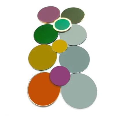
IAR8000-14000 Infrared Anti-Reflection Filter for 8–14 μm Systems
The IAR8000-14000 Infrared Anti-Reflection Filter fits thermal imaging, temperature measurement, and long-wave infrared instruments where the main goal is to reduce surface reflection across the 8–14 μm region. It does not replace a narrowband filter; selective rejection still requires an additional filter structure.
Custom Infrared Coating and Process Control for Nonstandard Specifications
A custom infrared multilayer coating is appropriate when standard parts cannot meet the required wavelength, edge steepness, blocking range, size, clear aperture, or incidence condition. Sample- and drawing-based development can help match an existing assembly. For procurement, the most useful input is a target spectral curve with measurement conditions, rather than a short note asking for “high transmission and deep blocking.”
What Should Buyers Confirm before Approving a Custom Coating?
Final approval should cover optical, mechanical, and environmental requirements together, not only a room-temperature spectrum.
A Complete Optical and Mechanical Specification
Define center wavelength, bandwidth, minimum transmission, maximum leakage, blocking interval, optical density if required, angle of incidence, polarization, and test temperature. Add substrate material, dimensions, thickness tolerance, surface quality, clear aperture, coated area, and edge condition. These items support feasibility review and inspection planning.
Prototype Validation, Environmental Reliability, and Maintenance Cost
Poor specification creates maintenance costs through recalibration, replacement, contamination, coating separation, or detector instability. Prototype testing should reproduce the real beam angle, temperature range, mounting stress, humidity exposure, and cleaning method.
For industrial procurement, the test plan can be tied to ISO 9211-3:2024, which assigns optical coatings to use categories and identifies the environmental tests required for each category. Cold, heat, and humidity exposure may be defined through ISO 9022-2:2015 and its 2023 amendment. Abrasion, adhesion, and resistance-to-water methods can be specified under ISO 9211-4:2022. The RFQ should state the test severity, duration, sample quantity, and acceptance criteria rather than request general “environmental resistance.”
After testing, buyers should compare the transmission curve, center wavelength, blocking performance, visible surface condition, edge integrity, haze, scratches, and signs of peeling against the pre-test results. A filter sealed inside an instrument may require a different qualification level from an exposed outdoor optical window, so the test category should follow the real installation.
Engineering Service, Sample Review, and Contact
BoDian Optical can review target curves, detector information, substrate drawings, incidence conditions, and expected order quantities before a coating route is fixed. Buyers who are comparing filter structures or preparing an RFQ can use the project contact channel to share the technical file set. Clear input reduces redesign, repeated sampling, and disputes over test conditions.
FAQ
Q: What information is needed to design an Infrared Multilayer Coating?
A: Provide the passband, blocking range, minimum transmission, permitted leakage, angle of incidence, temperature range, substrate, clear aperture, dimensions, and detector type. A target spectral curve is more useful than a center wavelength alone.
Q: Does adding more layers always improve infrared blocking?
A: No. More layers can deepen rejection, but they also increase absorption risk, thickness sensitivity, stress, and passband ripple. The layer count should follow the required blocking level and the stability of the deposition process.
Q: Should I choose a narrow bandpass filter or an anti-reflection filter?
A: Choose a narrow bandpass filter when the detector must isolate a defined wavelength. Choose an anti-reflection filter when the main goal is higher broadband transmission. Some instruments need both functions in one custom infrared optical coating.