English
 Afrikaans
 Albanian
 Amharic
 Arabic
 Armenian
 Azerbaijani
 Basque
 Belarusian
 Bengali
 Bosnian
 Bulgarian
 Catalan
 Cebuano
 Chichewa
 Chinese (Simplified)
 Chinese (Traditional)
 Corsican
 Croatian
 Czech
Czech Danish
 Dutch
Dutch Esperanto
 Estonian
 Filipino
 Finnish
 French
 Frisian
 Galician
 Georgian
 German
 Greek
Greek Gujarati
 Haitian Creole
 Hausa
Hausa Hawaiian
 Hebrew
 Hindi
Hindi Hmong
Hmong Hungarian
 Icelandic
 Igbo
Igbo Indonesian
 Irish
Irish Italian
 Japanese
 Javanese
 Kannada
 Kazakh
 Khmer
Khmer Korean
 Kurdish (Kurmanji)
 Kyrgyz
 Lao
Lao Latin
Latin Latvian
 Lithuanian
 Luxembourgish
 Macedonian
 Malagasy
 Malay
Malay Malayalam
 Maltese
 Maori
Maori Marathi
 Mongolian
 Myanmar (Burmese)
 Nepali
 Norwegian
 Pashto
 Persian
 Polish
 Portuguese
 Punjabi
 Romanian
 Russian
 Samoan
 Scottish Gaelic
 Serbian
 Sesotho
 Shona
Shona Sindhi
 Sinhala
 Slovak
 Slovenian
 Somali
 Spanish
 Sundanese
 Swahili
 Swedish
 Tajik
Tajik Tamil
Tamil Telugu
 Thai
Thai Turkish
 Ukrainian
 Urdu
Urdu Uzbek
Uzbek Vietnamese
 Welsh
Welsh Xhosa
Xhosa Yiddish
 Yoruba
 Zulu
Zulu


A NIR-Blocking Coating is intended to reduce unwanted near-infrared radiation, but the phrase “infrared blocking” does not tell an engineer enough to approve a coating. The useful questions are more specific: Which wavelengths are blocked? Is the rejected energy reflected or absorbed? How much light still passes through the coating? And were those values measured under conditions that match the final optical system?
For optical windows, imaging components, sensor covers, and thermal-control surfaces, the answer should come from spectral data rather than color, appearance, or a general blocking percentage.
BoDian Optical develops optical thin-film products across ultraviolet, visible, and infrared spectral regions. Its work includes coating design, substrate selection, customized optical filters, and spectral testing of transmittance, reflectance, and absorbance. These capabilities are relevant when a project moves from an initial coating concept to a measurable optical specification.
For readers first comparing material approaches, the related guide Which Paints and Pigments Block Near Infrared Light Effectively? discusses how paints and pigments can interact with near-infrared radiation.

What Does an NIR-Blocking Coating Actually Need to Control?
Before comparing products, define the spectral job. An NIR-Blocking Coating should not be approved simply because its supplier labels it “IR blocking.” The required wavelength range must come from the detector, light source, window, or thermal-control objective in the actual system.
The Relationship Between Wavelength and Infrared Blocking Performance
Infrared radiation begins at approximately 0.75 μm and extends across near-, mid-, and far-infrared regions. Optical systems do not necessarily use the entire infrared range, so the useful blocking region may occupy only part of it.
A transparent window may need strong visible transmission and NIR rejection, while an infrared detector may need a much more selective spectral boundary. That is why a specification should state the required transmission and rejection bands rather than use “blocks infrared” as the acceptance criterion.
The same principle applies during NIR reflectance measurement: data outside the actual operating band may be interesting, but it should not determine whether the coating is suitable for the project.
Reflection, Absorption, and Transmission Mechanisms
A coating can reduce transmitted NIR energy by reflecting it, absorbing it, or using a combination of optical effects. Thin-film coatings alter the transmission, reflection, and absorption behavior of incident light through material selection and multilayer design.
For a non-emitting sample, where the relevant transmitted and reflected energy is properly captured, the spectral balance can be written as:
A(λ) = 1 − T(λ) − R(λ)
Here, A(λ) is absorptance, T(λ) is transmittance, and R(λ) is reflectance at wavelength λ.
This relationship matters because two coatings can show similar low transmission while handling energy very differently. One may primarily reflect NIR, while another absorbs more of it and converts that energy to heat.
Measurements used in the comparison should therefore be taken under consistent conditions, especially the same angle of incidence, polarization state, substrate, and measurement geometry. For samples with meaningful scattering, the test method should also state whether total or only specular transmission and reflection are being measured.
Which Performance Parameters Should Engineers Compare When Selecting an NIR-Blocking Coating?
Once the target band is defined, the purchasing decision should move from marketing language to measurable limits. A useful specification describes both the pass region and the rejection region.
Spectral Transmittance, Reflectance, and Absorbance Data
A NIR coating spectral curve should show how the component behaves across the required wavelength range rather than provide only one headline number.
BoDian Optical’s testing capability covers transmittance, reflectance, and absorbance measurements for optical thin-film products across ultraviolet, visible, and infrared regions.
For coating approval, engineers should look at the curve for leakage peaks, edge position, variation across the blocking band, and any effect on the useful transmission region. If absorption is important to the application, T and R data should be considered together instead of treating low T alone as proof of good performance.
Visible Transparency and Target Band Compatibility
A transparent coating creates an obvious trade-off. Blocking unwanted NIR is useful only if the wavelengths required by the system remain sufficiently transmitted.
For glass, sensor covers, or imaging windows, compare the visible region and the NIR region on the same spectral report. A coating that provides strong attenuation but removes too much useful signal may solve one optical problem while creating another.
This is especially important for clear NIR-blocking coatings, where visual transparency alone cannot indicate infrared performance.
Substrate Compatibility and Optical System Requirements
The substrate is part of the optical system. Materials such as silicon, germanium, zinc sulfide, calcium fluoride, zinc selenide, and other optical substrates have different transmission windows and therefore influence the practical coating design.
Before approving a coating, confirm the actual substrate material and, where relevant, its thickness, surface condition, coating side, and operating environment. Comparing a coating tested on one substrate with a production component using another can produce misleading procurement decisions.
How Can NIR-Blocking Performance Be Verified Through Spectral Testing?
If the practical question is how to test NIR blocking coating performance, the answer begins with a repeatable test specification. A curve without measurement conditions is useful for screening, but it is weaker evidence for final design approval.
Define the Measurement Conditions Before Comparing Curves
A spectral test report should identify the required wavelength range and enough measurement conditions for another engineer to interpret or repeat the test.
For most coating comparisons, record:
- wavelength range;
- angle of incidence;
- polarization condition;
- substrate material;
- illuminated or measured side;
- beam or spot size;
- instrument spectral resolution or bandwidth;
- test temperature when temperature can affect the application.
Spectrometer bandwidth is especially relevant around sharp edges or narrow spectral features because finite instrument bandwidth can average features that are narrower than the measurement resolution. Filter test specifications also benefit from defining the equipment, acceptance limits, and measurement procedure in advance.
Compare Coated and Uncoated Samples on the Same Basis
Where practical, test the coated sample against an uncoated reference made from the same substrate. This separates the coating contribution from the substrate’s own spectral behavior.
For a nir-blocking coating, the comparison should use the same optical geometry, tested surface, wavelength interval, and instrument settings. Otherwise, a difference between two curves may come from the test configuration rather than the coating itself.
This method is particularly useful during sample approval because it gives engineering and purchasing teams a direct baseline before moving to production quantities.
Set Acceptance Metrics Before Production
“Good blocking” is not a measurable acceptance condition. The project should identify the spectral metrics that decide pass or fail.
| Specification Item | What It Helps Verify |
| Average Transmittance | Typical transmission across a defined pass or blocking band |
| Maximum or Peak Transmittance | Local transmission level or leakage peak, depending on the specified region |
| Optical Density (OD) | Rejection depth where very low transmission is required |
| Cutoff or Edge Wavelength | Position of the transition between transmission and rejection |
| Reflectance and Absorptance | Whether rejected energy is mainly reflected or absorbed |
| Spectral Uniformity | Performance variation across a component or production batch |
The appropriate limit must come from the application. Narrowband and edge-filter specifications, for example, become more sensitive to wavelength position, bandwidth, rejection and measurement method as system requirements become tighter.
When Is an Infrared Short Wave Pass Filter Relevant to NIR Blocking?
Coating qualification and system-level filtering are related but different tasks. The spectral performance of a coating should be verified directly from its measured data. An optical filter should not be added merely to make the coating appear to meet a blocking requirement.
However, some optical systems need a separate component that transmits shorter wavelengths while rejecting unwanted longer wavelengths. In that case, an infrared short wave pass filter can become relevant.
System-Level NIR Rejection Is Different from Coating Evaluation
A short-wave-pass filter is not the same product as an NIR-blocking paint or surface coating. Its role is to provide a designed spectral boundary within an optical system.
A well-established application of short-wave-pass filtering is transmitting visible wavelengths while blocking near-infrared radiation to reduce unwanted infrared response from a silicon receiver.
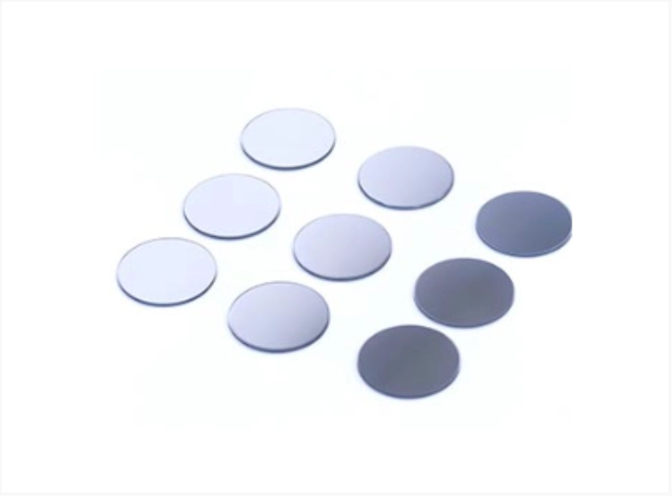
This makes BoDian Optical’s Infrared Short Wave Pass Filter category more closely related to system-level NIR rejection than an anti-reflection filter. The required cutoff and rejection region, however, still need to be selected from the actual source spectrum, detector response, and useful transmission band.
Short-Wave-Pass Selection Should Start with the System Specification
The category name alone is not enough to select a filter. Edge-filter design involves a pass region, a rejection region, edge position, ripple, and the interaction between thin-film materials and the substrate. Multilayer short-wave-pass structures can also require an extended rejection region when a single basic stack does not cover the full unwanted wavelength range.
For a new system, provide the desired transmission range, blocked range, incident angle, substrate constraints, and detector requirements before selecting a standard component or discussing a custom short-wave-pass filter.
How Should Buyers Specify and Source an NIR-Blocking Solution?
A useful RFQ should allow the coating engineer, system designer, and purchasing team to discuss the same optical target. This reduces the risk of comparing products that were measured or specified on different bases.
Convert the Application Requirement into a Test Specification
Before sending an inquiry, define:
- wavelengths that must pass;
- wavelengths that must be rejected;
- required T, R, or OD limits;
- permitted edge position;
- angle and polarization conditions;
- substrate and component dimensions;
- test conditions and sampling expectations.
Optical filter specifications are most useful when performance requirements, manufacturing requirements, and test requirements are treated as connected parts of the same project rather than independent documents.
Custom Optical Coating and Filter Support
BoDian Optical supports wavelength, size, thin-film design, and processing based on customer samples or drawings. Its product range includes infrared short-pass, long-pass, narrowband, broadband, and anti-reflection filter structures, allowing the optical approach to be selected around the application rather than forcing every project into the same filter type.
The practical goal is not to buy an “infrared blocking” label. It is to obtain a spectral response that can be measured against the final system requirement.
A NIR-Blocking Coating should be approved from defined spectral limits and repeatable test conditions. If your project has a target blocking band, cutoff requirement, detector response curve, substrate drawing, or existing spectral report, those materials give BoDian Optical a clearer basis for selection. Project details can be shared through the contact page for filter selection, coating design, or test requirement discussion.
FAQ
What Should I Check Before Choosing an NIR-Blocking Coating?
Start with the required wavelength range, then compare spectral transmittance, reflectance, and absorption behavior. Also confirm the substrate, angle of incidence, polarization, test side, and measurement conditions. An NIR-Blocking Coating should be selected from a defined spectral specification rather than a general infrared-blocking percentage.
How Do I Know Whether an NIR-Blocking Coating Works by Reflection or Absorption?
Measure both T(λ) and R(λ) under consistent conditions. Where the measurement captures the relevant transmitted and reflected energy, absorptance can be evaluated from A(λ) = 1 − T(λ) − R(λ). Low transmission alone does not show whether the rejected energy was reflected or absorbed.
Can a Short-Wave-Pass Filter Be Used Instead of an NIR-Blocking Coating?
They serve different integration needs. A surface coating changes the optical behavior of the coated component, while a short-wave-pass filter is a separate spectral-control element that can transmit shorter wavelengths and reject unwanted longer wavelengths. The choice depends on where NIR rejection must occur in the optical system.