English
 Afrikaans
 Albanian
 Amharic
 Arabic
 Armenian
 Azerbaijani
 Basque
 Belarusian
 Bengali
 Bosnian
 Bulgarian
 Catalan
 Cebuano
 Chichewa
 Chinese (Simplified)
 Chinese (Traditional)
 Corsican
 Croatian
 Czech
Czech Danish
 Dutch
Dutch Esperanto
 Estonian
 Filipino
 Finnish
 French
 Frisian
 Galician
 Georgian
 German
 Greek
Greek Gujarati
 Haitian Creole
 Hausa
Hausa Hawaiian
 Hebrew
 Hindi
Hindi Hmong
Hmong Hungarian
 Icelandic
 Igbo
Igbo Indonesian
 Irish
Irish Italian
 Japanese
 Javanese
 Kannada
 Kazakh
 Khmer
Khmer Korean
 Kurdish (Kurmanji)
 Kyrgyz
 Lao
Lao Latin
Latin Latvian
 Lithuanian
 Luxembourgish
 Macedonian
 Malagasy
 Malay
Malay Malayalam
 Maltese
 Maori
Maori Marathi
 Mongolian
 Myanmar (Burmese)
 Nepali
 Norwegian
 Pashto
 Persian
 Polish
 Portuguese
 Punjabi
 Romanian
 Russian
 Samoan
 Scottish Gaelic
 Serbian
 Sesotho
 Shona
Shona Sindhi
 Sinhala
 Slovak
 Slovenian
 Somali
 Spanish
 Sundanese
 Swahili
 Swedish
 Tajik
Tajik Tamil
Tamil Telugu
 Thai
Thai Turkish
 Ukrainian
 Urdu
Urdu Uzbek
Uzbek Vietnamese
 Welsh
Welsh Xhosa
Xhosa Yiddish
 Yoruba
 Zulu
Zulu


Signal noise in MWIR Medical Imaging is often caused by a mix of unwanted spectral energy, optical loss, reflections, detector response mismatch, and unsuitable filter specifications. A detector may be working normally while the optical path still delivers too much background radiation or too little useful signal. For medical imaging and infrared detection equipment, the filter should therefore be checked as part of the complete optical chain rather than treated as an isolated accessory.

Why Does Signal Noise Appear in MWIR Medical Imaging Systems?
Before changing detectors or image-processing settings, engineers should determine whether part of the noise is entering through the optical path. Thin-film filters control which wavelengths pass, reflect, or are absorbed. If that control does not match the actual detector and target spectrum, image contrast and measurement stability can suffer.
Out-of-Band Radiation Reaches the Detector
An infrared detector may respond to a wider spectral range than the system actually needs. Radiation outside the useful band can reach the sensing surface together with the target signal. That extra energy increases the background level and can lower the signal-to-noise ratio in infrared imaging.
A filter helps by defining a controlled spectral window before radiation reaches the detector. The purpose is not simply to block “more light.” The passband needs to preserve useful infrared energy while the rejection region suppresses wavelengths that contribute little to the measurement.
Optical Losses Reduce the Useful Signal
Noise can also become more visible when the useful signal is weakened. Reflection at optical interfaces, absorption in the substrate, and losses within the coating structure all affect how much radiation reaches the detector.
This is why filter evaluation normally considers transmittance, reflectance, and absorbance together. A passband may be positioned correctly, yet the system can still perform poorly if too much useful energy is lost along the optical path.
BoDian Optical develops optical thin-film filters for infrared imaging, infrared detection, healthcare equipment, temperature measurement, instrumentation, and related optical systems. Its infrared range includes broadband, narrowband, long-pass, short-pass, and anti-reflection filters. The company also supports customized wavelength, size, substrate, and structural requirements, which is useful when a catalog filter cannot directly match the detector or mechanical layout.
Filter and Detector Spectral Mismatch Lowers Signal Quality
The word “MWIR” alone is not enough for filter selection. The detector response curve, lens transmission, target spectrum, filter passband, and operating geometry need to overlap in the intended region.
For mwir medical imaging, a filter that passes wavelengths near the edge of the detector response may waste part of the available signal. The practical rule is simple: compare the proposed filter curve with the actual detector response before approving the optical specification.
How Can Broadband Filtering Improve MWIR Medical Imaging?
Broadband filtering is useful when the device needs to collect information across a wider section of the mid-wave infrared region instead of isolating one narrow spectral feature. In such systems, the filter defines the usable infrared window and keeps unrelated radiation away from the detector.
Passing the Required Band While Rejecting Unwanted Radiation
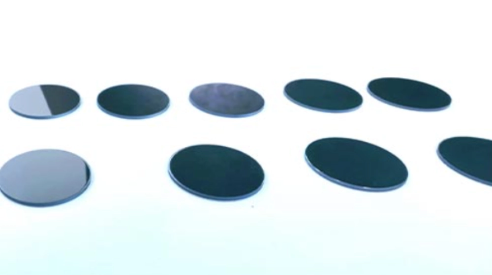
For systems designed around 3–5 μm transmission, the IWBP3000-5000 Infrared Broad-Band Pass Filter provides a practical reference point. The current product specification lists a Si substrate, a 3000–5000 nm HT area, Tp ≥85%, and blocking from 1500 to 11000 nm. Its listed applications include infrared detectors and medical apparatus and instruments.
These values matter together. A wide passband without suitable infrared filter spectral blocking can still allow background energy into the detector. Deep blocking without enough useful transmission can create the opposite problem by weakening the wanted signal.
Matching the 3–5 μm Range to the Imaging System
A 3–5 μm infrared bandpass filter should only be selected when the detector and optical system actually need this region. Infrared materials have different transmission windows, and the substrate must remain suitable across the working wavelength.
The IWBP3000-5000 uses silicon. Other infrared filter designs may use germanium, sapphire, calcium fluoride, zinc sulfide, or zinc selenide, depending on spectral and mechanical requirements. These materials should not be treated as interchangeable simply because they are all used in infrared optics.
Broadband and Narrowband Filters Serve Different Detection Tasks
Broadband filters preserve a wider spectral interval. Narrowband filters isolate a more specific wavelength region. For medical infrared detection equipment, the correct type depends on what the detector is expected to distinguish.
One useful technical distinction is bandwidth relative to center wavelength. A half bandwidth within 6% of the center wavelength is classified as narrowband, while a larger value is treated as broadband. This does not mean narrower bandwidth always produces a better result. The filter bandwidth should follow the measurement task.
Which Specifications Matter When Selecting an MWIR Medical Imaging Filter?
A useful purchase specification needs more than a product category or nominal wavelength. Engineers should define the transmission region, rejection region, substrate, optical aperture, dimensions, surface condition, and installed optical geometry.
Passband, Peak Transmittance, and Blocking Range
Passband and blocking requirements should be written as measurable spectral conditions rather than broad terms such as “high transmission” or “deep blocking.” For medical imaging equipment, the filter specification should show where useful radiation must pass, where unwanted radiation must be rejected, and how those limits are verified during incoming inspection.
For the IWBP3000-5000, the currently published specifications provide a practical starting point:
| Specification | Published Value | What Buyers Should Check for Medical MWIR |
| Substrate | Si | Confirm compatibility with the operating wavelength, mechanical layout, and coating design |
| HT Area | 3000–5000 nm | Overlay the passband with the actual detector responsivity curve |
| Peak Transmittance (Tp) | ≥85% | Confirm that sufficient useful infrared energy reaches the detector |
| Blocking Range | 1500–11000 nm | Define the required rejection depth across the detector-sensitive out-of-band region |
| Optical Density | Project-specific | Specify OD3, OD4, or another level according to allowable leakage and detector sensitivity |
| Surface Quality | Project-specific | Define acceptable scratches, pits, edge defects, and polishing condition in the drawing |
| Parallelism | Project-specific | Set the allowable value from beam deviation and image registration requirements |
| Clear Aperture | Project-specific | Define the usable optical area from the actual beam footprint and mounting margin |
Optical density should be treated as an acceptance requirement rather than assumed from the blocking wavelength range. OD3 corresponds to 0.1% transmission, OD4 to 0.01%, and OD5 to 0.001%. A deeper OD target reduces out-of-band leakage, but it should only be specified where the detector response and unwanted background justify it. Requiring unnecessarily deep blocking can make the coating design more complex without improving the final image.
Mechanical and surface requirements should be handled in the same way. BoDian Optical’s inspection scope includes dimensions, tolerances, surface condition, chipped edges, cracks, polishing quality, and clear aperture. For mwir medical imaging, the buyer should convert these into drawing-level acceptance limits based on the real optical path. A scratch-dig grade, parallelism tolerance, or clear-aperture percentage should only be written as a fixed number when the project specification or supplier-confirmed drawing supports it.
A filter can therefore meet its nominal 3000–5000 nm passband and still cause problems after installation if surface scattering, aperture restriction, or beam deviation affects the detector field. For medical imaging systems, spectral and mechanical acceptance should be reviewed together rather than approved as separate items.
Substrate Material Must Match the Optical System
The substrate carries the coating but also participates in the optical path. It needs to transmit the required infrared region and remain compatible with the coating process, thickness requirement, surface specification, and assembly method.
Silicon, germanium, sapphire, calcium fluoride, zinc sulfide, and zinc selenide cover different spectral and physical requirements. Selecting one only because it is commonly used in infrared systems can create avoidable loss or integration problems. Working wavelength and mechanical layout should come first.
Aperture, Surface Quality, and Incidence Conditions Affect Performance
A correct spectral curve does not guarantee correct system performance if the usable optical area is too small. The clear aperture should match the beam footprint rather than just the outside diameter of the filter.
Surface inspection also matters. Dimensions, edge damage, cracks, polishing condition, and usable aperture are part of filter acceptance. In a compact optical module, an undersized clear aperture can restrict the beam even though the coating itself meets the spectral requirement.
Angle of incidence is another common source of mismatch. Interference-filter spectra can shift toward shorter wavelengths as the incident angle increases. A tilted holder, wide field of view, or converging beam should therefore be stated before sample approval.
What Should Buyers Verify Before Integrating an MWIR Filter?
Catalog specifications are useful for screening products, but system qualification should be done with the real optical assembly. That is where spectral, mechanical, and detector-related problems become easier to separate.
Spectral Performance Should Be Verified Before Integration
Spectral inspection should confirm the transmission region and blocking region under agreed test conditions. Transmittance T, reflectance R, and absorbance ABS provide different views of how the filter handles incoming radiation.
A supplier and buyer should also use consistent reference conditions. Changes in test angle, measurement aperture, spectral range, or calculation method can make two curves appear different even before the filter itself is questioned.
Prototype Testing Reveals System-Level Noise Problems
Prototype testing is more useful when the filter is installed with the actual detector, lens, aperture, and mounting geometry. If noise remains, the engineering team can then determine whether the cause is spectral leakage, reflection, insufficient useful transmission, detector response, or electronics.
This step is especially valuable in mwir medical imaging, where the optical filter is only one part of the signal chain. Replacing the filter repeatedly without identifying the failure mode can extend sampling cycles without solving the real problem.
Manufacturing Consistency Matters Beyond the First Sample
Thin-film coating performance depends on layer thickness, uniformity, substrate preparation, and process control. Thickness errors can change wavelength position or passband shape, and more selective filter structures generally require tighter control.
For repeat orders, buyers should confirm that the same acceptance conditions used for the approved sample also apply to production inspection. Spectral position, transmission, blocking, dimensions, clear aperture, and surface condition should all have defined limits.
How Can Buyers Reduce Risk from Sampling to Production?
Many integration problems start before coating begins. A clear RFQ gives the optical team enough information to determine whether a catalog filter can be used or whether the coating and substrate need to be adjusted.
Define the Optical Requirement Before Requesting Samples
A useful request should include the required passband or center wavelength, blocking interval, transmission requirement, detector response, nominal angle of incidence, beam cone or field of view, substrate preference, outside dimensions, clear aperture, operating environment, and drawing where available.
These details are more useful than requesting a “MWIR filter” without system information. They also make sample approval easier because both sides have measurable acceptance conditions.
Use IWBP3000-5000 When the System Requires Broad 3–5 μm Transmission
IWBP3000-5000 is worth considering where a MWIR filter for medical imaging needs broad transmission from 3000 to 5000 nm and the Si substrate fits the rest of the optical design. The product should not be selected only because the equipment operates somewhere in the MWIR region.
The detector curve should still be checked first. If the useful signal occupies a much narrower region, a broadband filter may admit more spectral energy than necessary. If the required range is broader or shifted, a standard 3000–5000 nm window may remove useful signal.
Contact BoDian Optical for Custom MWIR Filter Service
BoDian Optical’s custom filter service covers infrared broadband, narrowband, long-pass, short-pass, and anti-reflection filters, with customization for wavelength, size, and frame or structural requirements. The company states that it can support work from prototype design to mass production and can test T, R, and ABS across ultraviolet, visible, and infrared ranges.
For a MWIR Medical Imaging project, prepare the detector response, required transmission band, blocking range, dimensions, clear aperture, mounting angle, and operating conditions before technical review. If the main difficulty is choosing between a standard broadband filter and a modified coating design, these details can be sent through the project contact channel.
FAQ
What Type of Filter Is Used for MWIR Medical Imaging?
Broadband filters are suitable when MWIR Medical Imaging needs a wider spectral window, such as a system designed around 3–5 μm transmission. Narrowband filters are more appropriate when the detector must isolate a specific wavelength feature. The detector response and target spectrum should determine the final choice.
Can a 3–5 μm Filter Reduce Noise in an Infrared Imaging System?
Yes, if the useful signal lies within that range and unwanted radiation outside it contributes to the background. A 3–5 μm filter cannot correct detector readout noise or electronic noise, so the optical and electronic causes should be separated during prototype testing.
What Information Should Be Provided for a Custom MWIR Filter?
Provide the required passband, blocking interval, transmission target, detector response, substrate preference if known, dimensions, clear aperture, angle of incidence, beam geometry, and operating conditions. These details allow the filter design to follow the actual optical path rather than a generic MWIR category.