English
 Afrikaans
 Albanian
 Amharic
 Arabic
 Armenian
 Azerbaijani
 Basque
 Belarusian
 Bengali
 Bosnian
 Bulgarian
 Catalan
 Cebuano
 Chichewa
 Chinese (Simplified)
 Chinese (Traditional)
 Corsican
 Croatian
 Czech
 Danish
 Dutch
 Esperanto
 Estonian
 Filipino
 Finnish
 French
 Frisian
 Galician
 Georgian
 German
 Greek
 Gujarati
 Haitian Creole
 Hausa
 Hawaiian
 Hebrew
 Hindi
 Hmong
 Hungarian
 Icelandic
 Igbo
 Indonesian
 Irish
 Italian
 Japanese
 Javanese
 Kannada
 Kazakh
 Khmer
 Korean
 Kurdish (Kurmanji)
 Kyrgyz
 Lao
 Latin
 Latvian
 Lithuanian
 Luxembourgish
 Macedonian
 Malagasy
 Malay
 Malayalam
 Maltese
 Maori
 Marathi
 Mongolian
 Myanmar (Burmese)
 Nepali
 Norwegian
 Pashto
 Persian
 Polish
 Portuguese
 Punjabi
 Romanian
 Russian
 Samoan
 Scottish Gaelic
 Serbian
 Sesotho
 Shona
 Sindhi
 Sinhala
 Slovak
 Slovenian
 Somali
 Spanish
 Sundanese
 Swahili
 Swedish
 Tajik
 Tamil
 Telugu
 Thai
 Turkish
 Ukrainian
 Urdu
 Uzbek
 Vietnamese
 Welsh
 Xhosa
 Yiddish
 Yoruba
 Zulu



Calibration becomes difficult when the infrared signal from an SF₆ leak monitor won’t stay steady, or is weak to begin with. It’s worth checking what actually reaches the detector before adjusting the calibration again. If the SF6 gas detection filter passes the wrong part of the spectrum, that matters. Look at where the band sits, how wide it is, and the rejection outside it.
Bodian Optical makes optical thin-film components; INBP10560 is its filter for SF₆ gas detection. The number to look at first is 10.56 μm. From there, the job moves to the transmission figures and a sample in the prototype. Matching the wavelength is helpful, but it doesn’t finish the optical design.
Why Is 10.56 μm Important for SF₆ Gas Detection?
An absorption instrument relies on radiation being lost as it travels through the gas. That loss isn’t the same at every wavelength. So the band selected for measurement has to follow the gas absorption, rather than simply whatever radiation the detector can receive.
A Strong SF₆ Absorption Feature Near 10.56 μm
Near 10.55 μm, SF₆ has a pronounced absorption feature. This is why a channel close by, at 10.56 μm, is of interest. How much radiation is absorbed also changes with the amount of gas and the length of the path through it. The SF6 gas absorption wavelength is thus a useful reference for the design, without making this the only possible channel arrangement.
The Need for Selective Infrared Transmission
The detector may be sensitive to a lot more radiation than the gas measurement needs. Letting all of it through brings background energy into the reading as well. Restricting the channel with a narrow bandpass filter helps separate the wanted region. Before choosing one, lay its curve alongside the gas spectrum and detector response. Electronic noise is a separate issue that this optical part won’t cure.
How Does a 10.56 μm Bandpass Filter Improve SF₆ Detection?
Start with the band position, then look at its width and the radiation getting through outside it. All three affect what is available to measure.
Precise Transmission Around the Target Wavelength
The center wavelength (CWL) for INBP10560 is 10560 ± 70 nm. On paper, that puts the filter close to the desired gas absorption region. For selection, the curve is more revealing than the center number alone: a band shifted away from the feature can give a different signal. How much shift can be accepted needs deciding for the particular sensor.
Bandwidth and Signal Strength Balance
INBP10560’s half-power bandwidth (HPB) is 240 ± 20 nm. Reducing the width isn’t a free improvement. There is less unwanted radiation, but there may also be less signal to work with. A wider band can bring more energy, some at wavelengths where the gas absorbs less strongly. With a 10.56 μm infrared filter, the source, absorption curve, and detector noise need to be part of that decision together.
Out-of-Band Rejection for Cleaner Detection
Blocking is specified over 400–14000 nm, with less than 1% transmission outside the passband. Read that last qualification carefully: it doesn’t say that the filter blocks the band needed for measurement. Look for unwanted transmission near any interfering absorption regions. There’s a separate discussion of infrared-blocking paints and pigments, but those coatings control radiation broadly and aren’t substitutes for a sensing filter.
Which INBP10560 Specifications Matter Most When Selecting a Filter?
Use the following INBP10560 figures as the starting point for SF6 gas sensor filter selection. The optical path and sample acceptance conditions still need to be checked against them.
| Specification | Published Value |
| Substrate | Ge (germanium) |
| Center wavelength (CWL) | 10560 ± 70 nm |
| Half-power bandwidth (HPB) | 240 ± 20 nm |
| Peak transmission (Tp) | ≥90% |
| Blocking | 400–14000 nm, T <1% outside the passband |
High Peak Transmission for Useful Signal Collection
At the top of the passband, transmission is specified as at least 90%. It would be a mistake to use that peak as though the whole band transmitted equally. With a weak source or a long gas path, the loss elsewhere in the curve deserves particular attention. Use that curve for the energy estimate. The INBP10560 product page gives the component figures to begin the comparison.
Germanium Substrate for Infrared Optical Integration
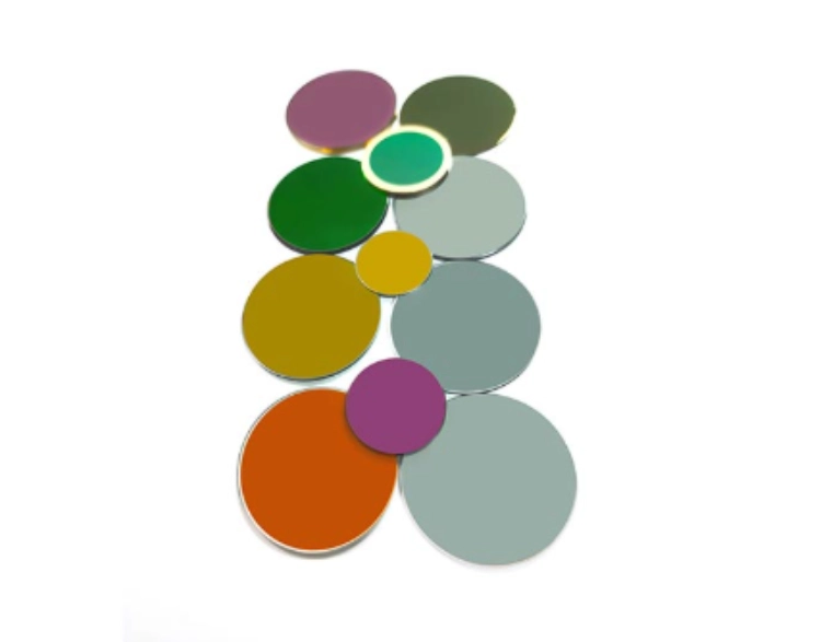
The substrate is Ge. That tells the buyer which material is used, while the coating is what sets the filter’s passband. There are other possible losses along the path as well, through the windows, lenses, and detector package. Before approving the part, put its dimensions against the housing drawing. The clear aperture, handling, and operating conditions also need checking.
Wavelength Tolerance and Operating Conditions
Don’t read ±70 nm as a promise covering every condition in service. It is the CWL manufacturing tolerance. Changing the angle can move an interference filter’s spectrum, and a converging beam reaches the surface at a range of angles rather than just one. Tell the supplier that range and the working environment. Temperature behavior needs checking for the conditions the sensor will face too.
How Can Engineers Verify INBP10560 Performance in an SF₆ Sensor?
A correct part number doesn’t finish the verification. The SF6 gas detection filter has to work in the assembled instrument, with incoming inspection and calibration covering the same optical design.
Matching the Filter to the Optical Detection System
Start at the source and follow the radiation through the instrument. There has to be usable output in the required band and a detector response there, with transmission through the gas cell windows and other optics taken into account. The length of the gas path and its concentration change the absorption. That’s the layout in which an infrared filter for SF6 detection has to earn approval.
Spectral Testing Before System Integration
The sample should arrive with a spectral record, before installation. Compare CWL, HPB, peak transmission, and rejection outside the passband with the agreed values. Note which way the part is mounted and look for stray light. Different incidence angles between the supplier’s test and the instrument call for another response check. Otherwise an optical mismatch can be hidden by later calibration adjustments.
Reference Channels and Calibration Checks
Many instruments compare the measurement signal with a reference channel outside the target band. That comparison helps track source output and background changes. The reference itself needs to stay clear of SF₆ and interfering absorption features. Known gas conditions are still required for calibration. A filter doesn’t report concentration by itself, nor can it promise a detection limit.
What Should Buyers Confirm with Bodian Optical Before Ordering?
A wavelength alone doesn’t tell a supplier enough about the sensor. Include the layout and agree on the sample checks before ordering.
Optical and Mechanical Requirements for Filter Selection
A useful inquiry includes the source and detector details, target band, and gas path length. The supplier also needs the beam angle and temperature range, how much mounting space is available, and the quantity. For a bandpass filter for gas detection, say which channels are for measurement and reference. Include any transmission or blocking needs beyond the catalog specification.
Product Customization and Sample Validation
Perhaps the design calls for a different size, aperture, or tighter spectral tolerance. In that case, the catalog entry is only a starting point and a custom part can’t be treated as interchangeable with it. Agree on the measurement conditions for samples before ordering. Also settle which records are to accompany the parts, so acceptance doesn’t depend on assumptions made by either side.
Bodian Optical Service and Contact Support
Bodian Optical can discuss how a filter specification fits a proposed application. An optical drawing and performance targets are useful here. Include the package dimensions and beam angle, and explain the interval where blocking is needed; those details give the technical discussion a concrete basis.
Conclusion
For an SF₆ instrument, 10.56 μm points to a useful absorption region. Before selecting INBP10560, work through what its bandwidth, transmission, blocking, and wavelength tolerance mean in that instrument. The final check belongs in the calibrated system. A matching number on an SF6 gas detection filter doesn’t replace that check before production.
Project Support and Contact
For weak signals or inconsistent prototype readings, assemble the optical drawing and the source and detector details first. Add the spectral requirements and working conditions, then contact Bodian Optical to discuss the match with INBP10560. If the design calls for adjustments, raise them before ordering samples.
FAQ
Q: Can one SF6 gas detection filter work with every SF₆ sensor?
A: No, because the same nominal wavelength can be used in quite different optical layouts. Check it against the source, detector, and gas absorption channel of the actual sensor.
Q: Why not choose the narrowest possible bandpass filter?
A: Making it narrower also takes away some of the signal. The gas spectrum helps identify unwanted wavelengths, but the detector still needs enough radiation for the instrument to work. Both needs have to fit the chosen bandwidth.
Q: Is a 10.56 μm filter enough to measure SF₆ concentration?
A: No; passing a selected band is just the filter’s part of the job. A concentration reading needs the source, gas path, detector, and signal processing to work together, with calibration under known conditions.