English
 Afrikaans
 Albanian
 Amharic
 Arabic
 Armenian
 Azerbaijani
 Basque
 Belarusian
 Bengali
 Bosnian
 Bulgarian
 Catalan
 Cebuano
 Chichewa
 Chinese (Simplified)
 Chinese (Traditional)
 Corsican
 Croatian
 Czech
Czech Danish
 Dutch
Dutch Esperanto
 Estonian
 Filipino
 Finnish
 French
 Frisian
 Galician
 Georgian
 German
 Greek
Greek Gujarati
 Haitian Creole
 Hausa
Hausa Hawaiian
 Hebrew
 Hindi
Hindi Hmong
Hmong Hungarian
 Icelandic
 Igbo
Igbo Indonesian
 Irish
Irish Italian
 Japanese
 Javanese
 Kannada
 Kazakh
 Khmer
Khmer Korean
 Kurdish (Kurmanji)
 Kyrgyz
 Lao
Lao Latin
Latin Latvian
 Lithuanian
 Luxembourgish
 Macedonian
 Malagasy
 Malay
Malay Malayalam
 Maltese
 Maori
Maori Marathi
 Mongolian
 Myanmar (Burmese)
 Nepali
 Norwegian
 Pashto
 Persian
 Polish
 Portuguese
 Punjabi
 Romanian
 Russian
 Samoan
 Scottish Gaelic
 Serbian
 Sesotho
 Shona
Shona Sindhi
 Sinhala
 Slovak
 Slovenian
 Somali
 Spanish
 Sundanese
 Swahili
 Swedish
 Tajik
Tajik Tamil
Tamil Telugu
 Thai
Thai Turkish
 Ukrainian
 Urdu
Urdu Uzbek
Uzbek Vietnamese
 Welsh
Welsh Xhosa
Xhosa Yiddish
 Yoruba
 Zulu
Zulu


Infrared reflection loss can occur whenever radiation crosses an interface between air and an optical window, lens, filter, or other optical material. A detector may have sufficient sensitivity, yet the useful energy reaching it can still be lower than expected because part of the incident radiation is reflected at each surface. As more optical elements are added, these losses can accumulate and affect system transmission, contrast, and measurement reliability.
BoDian Optical focuses on optical coating technology and thin-film optical products for infrared detection, thermal imaging, temperature measurement, gas analysis, remote sensing, and other optical systems. Its capabilities cover substrate selection, coating, spectral testing, and customized wavelength, size, and film-design requirements. Transmittance, reflectance, and absorbance can be measured across ultraviolet, visible, and infrared wavelength ranges, which helps engineers identify where optical energy is being lost instead of relying on a single transmission value.

What Causes Reflection Loss at Infrared Optical Interfaces?
Infrared reflection loss is primarily an interface effect. When adjacent optical media have different refractive indices, part of the incident energy is transmitted while another part is reflected. The scale of that reflection depends on the optical materials, wavelength, angle of incidence, and coating condition.
Refractive-Index Mismatch Produces Fresnel Reflection
At normal incidence, surface reflectance can be approximated by:
R = [(n₁ − n₂) / (n₁ + n₂)]²
The larger the refractive-index difference between adjacent media, the greater the potential surface reflection. This is why Fresnel reflection in infrared optics becomes especially relevant when high-index substrates are placed next to air.
Infrared substrates can have much higher refractive indices than common visible-light glass, so bare surfaces require more attention during system design. High-index infrared components often need an AR coating if the goal is to preserve useful transmission through the complete optical path.
High-Index Infrared Substrates Can Have Significant Bare-Surface Loss
The effect can be large enough to influence the optical energy budget directly. Silicon, for example, has a refractive index of approximately 3.5 under the reference conditions discussed in thin-film coating theory and can produce about 31% reflection loss per bare surface.
This illustrates an important distinction: a substrate can transmit infrared radiation internally while still losing a substantial portion of incident energy at its surface.
For a material-specific example of how refractive index, transmission, and coating requirements interact, see BoDian’s guide to Germanium in infrared optics. Material selection is only one part of the problem; the complete optical path still determines the final system throughput.
Multiple Optical Surfaces Compound System-Level Loss
A typical infrared optical train may include a protective window, several lens surfaces, a filter, and a detector window. Reflection at each interface means that infrared optical transmission through the whole assembly can be lower than the specification of any individual component suggests.
Reflections from multiple untreated surfaces can also follow unintended optical paths and contribute to ghost images or veiling glare at the focal plane. That can reduce contrast even when the detector itself is operating normally.
For this reason, infrared reflection loss should be evaluated across the complete optical train rather than assigned to one filter alone.
Why Does Reflection Loss Matter Before Infrared Light Reaches the Detector?
The effect becomes easier to judge when the optical path is treated as an energy chain rather than a collection of separate components:
Target Radiation → Window → Lens → Filter → Detector
The detector only receives the portion of radiation that remains after transmission, reflection, absorption, and other losses along that path.
Less Useful Infrared Energy Reaches the Detector
Each surface reflection removes part of the radiation from the intended beam. With several optical interfaces in series, the cumulative effect can reduce the useful signal reaching the sensor.
This does not mean an AR coating changes the detector’s intrinsic sensitivity. It means reducing avoidable reflection can improve IR optical system throughput, allowing more of the useful radiation to reach the detector.
A component with an attractive peak transmission value may therefore still perform poorly in a system if other surfaces introduce significant losses.
Reflected Energy Can Reduce Image and Measurement Quality
Reflection can create two problems at the same time.
The first is straightforward energy loss. The second is unwanted reflected radiation traveling along another optical path.
In imaging systems, this may contribute to reduced contrast, ghosting, or stray-light artifacts. In measurement equipment, unwanted reflections may interfere with the useful signal. The actual effect depends on the optical geometry, number of surfaces, detector response, wavelength range, and surface treatment.
Reflection Loss Should Be Separated from Absorption and Scattering
Low transmission does not automatically mean excessive reflection.
Transmittance, reflectance, and absorbance should be evaluated as separate spectral properties rather than inferred from transmission alone. BoDian’s optical testing capability includes T, R, and ABS measurements for this reason.
If a system shows unexpectedly low transmission, engineers should first determine whether the missing energy is being reflected, absorbed, or scattered. An infrared anti-reflection coating is useful when surface reflection is a meaningful part of the problem, but it cannot correct absorption inside an unsuitable substrate.
How Do Infrared Anti-Reflection Coatings Reduce Reflection Loss?
Once reflection has been identified as a significant loss mechanism, the coating can be designed around the substrate, operating wavelength, and required optical geometry.
The goal is not simply to apply an additional film. The film structure must control the amplitude and phase of reflected waves so that less energy returns toward the incident side.
Thin-Film Interference Suppresses Reflected Waves
An AR coating creates additional reflections at its thin-film interfaces. With suitable refractive indices and optical thicknesses, these reflected components can interfere destructively.
The basic single-layer case uses approximately quarter-wave optical thickness. More demanding spectral requirements usually require multilayer structures that control reflection across a wider wavelength range.
This is the basic thin-film approach used to reduce reflection in infrared optics.
Multilayer Designs Extend Low Reflection Across the Working Band
A coating optimized around one wavelength is not automatically suitable for a wide infrared band.
AR structures can range from relatively simple coatings intended for a limited region to multilayer designs intended to maintain lower reflection across broader spectral ranges. Substrate refractive index, operating wavelength, target performance, and manufacturing practicality all affect the design.
Engineers can begin with BoDian’s Infrared Anti-Reflection Filter category and then narrow the selection according to the useful detector band rather than choosing a model only by its nominal range.
BoDian IAR Filters Address Different Spectral Requirements
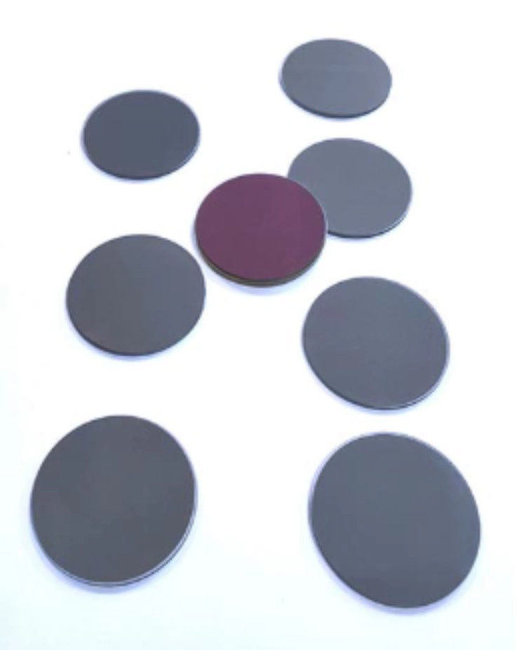
For systems concentrated in the 3–5 μm region, the IAR3000-5000 Infrared Anti Reflection Filter provides a practical reference. It uses a Si substrate, specifies a 3000–5000 nm high-transmission area, and has Tavg ≥98%. Listed applications include industrial temperature measurement, power inspection, remote sensing, and infrared thermal imaging.
A system requiring substantially wider infrared coverage has a different design target. The IAR2000-16000 Infrared Anti Reflection Filter uses a ZnSe substrate, specifies a 2000–16000 nm high-transmission area, and has Tavg ≥90%.
| Product | Substrate | High-Transmission Area | Tavg | Selection Logic |
| IAR3000-5000 Infrared Anti Reflection Filter | Si | 3000–5000 nm | ≥95% | Optical systems concentrated in the 3–5 μm range |
| IAR2000-16000 Infrared Anti Reflection Filter | ZnSe | 2000–16000 nm | ≥90% | Systems requiring broader infrared spectral coverage |
The wider range is not automatically more suitable. The useful AR band should match the wavelengths that actually need to reach the detector.
How Should Engineers Choose an AR Filter for Their Infrared System?
Reducing infrared reflection loss starts with the system specification rather than the product code. Wavelength range, detector response, substrate, optical geometry, and operating conditions should be defined before the coating is selected.
Match the Coating Band to the Detector and Working Wavelength
Start with the wavelengths that contain useful information for the application. Then check whether the detector responds efficiently in that region and whether the window, lens, filter substrate, and coating can transmit it.
A system working mainly from 3–5 μm does not automatically benefit from specifying an extremely broad coating range. Conversely, a broad-spectrum detector should not be paired with an AR design that performs well only over a narrow section of its response band.
This is the central principle behind practical infrared AR filter selection: define the system band first, then specify the coating.
Evaluate Average Transmission, Reflectance, and Angle of Incidence
Peak transmission alone is not enough for procurement decisions.
A useful RFQ should specify the working wavelength range, average transmission target, reflectance requirement, angle of incidence, and polarization conditions where relevant. Filter requirements should also account for what can actually be manufactured and measured under the intended system conditions.
Angle of incidence deserves particular attention because changing the incidence angle changes the optical phase thickness and can move the wavelength associated with minimum reflection.
Check the Substrate, Surface Quality, and Environmental Conditions
Spectral performance should be checked separately from dimensions, surface quality, and clear aperture because all of these affect whether the coated component is acceptable in the assembled system.
BoDian evaluates dimensional tolerance, surface condition, optical aperture, and spectral properties as separate product characteristics.
For custom projects, operating temperature, humidity exposure, installation geometry, and adjacent optical components should also be discussed before the coating design is finalized.
What Should Buyers Send to BoDian Optical Before Ordering?
A useful RFQ should describe the optical problem rather than asking only for “an infrared AR filter.” This allows the coating engineer to judge whether a standard product is appropriate or whether the wavelength range, substrate, or coating design should be adjusted.
Define the Optical and Mechanical Specification
Provide the working wavelength range, target transmission or reflectance, substrate, component dimensions, clear aperture, AOI, operating environment, and application.
If infrared reflection loss has already been measured, supplying the available T/R spectral curve can help distinguish a surface-reflection problem from substrate absorption or another loss mechanism.
Custom Coating and Spectral Testing Support Nonstandard Requirements
BoDian can customize wavelength, size, and film design and supports processes from substrate selection through coating and testing. Its manufacturing capabilities include vacuum evaporation and magnetron sputtering, while spectral evaluation covers T, R, and ABS.
Custom coating becomes relevant when a standard infrared anti-reflection coating does not match the required spectral band, substrate, or optical geometry.
Contact BoDian Optical for an Application-Specific AR Solution
If your project has an unusual working band, AOI constraints, uncertain substrate selection, or measured transmission that does not match the system target, include those conditions when you contact BoDian Optical. Providing the wavelength range, substrate, dimensions, T/R targets, and available spectral data makes it easier to address infrared reflection loss without adding unnecessary specifications.
FAQ
What is the main cause of infrared reflection loss in an optical system?
One major cause is refractive-index mismatch at optical interfaces. Part of the incident radiation is reflected whenever light passes between media with different optical indices. Systems containing multiple windows, lenses, and filters can accumulate these losses across several surfaces.
Does a higher-transmission AR filter always reduce infrared reflection loss more effectively?
No. Transmission must be evaluated across the actual working wavelength range and at the intended angle of incidence. A high transmission value at one wavelength does not guarantee suitable performance across the complete detector band or optical geometry.
Should I choose a 3–5 μm AR filter or a broad-spectrum infrared AR filter?
Match the coating range to the useful spectrum of the system. A system focused on 3–5 μm can use an AR design optimized for that region, while broader detection requirements may justify a wider coating range. Substrate, AOI, transmission targets, and mechanical requirements should be specified at the same time.