English
 Afrikaans
 Albanian
 Amharic
 Arabic
 Armenian
 Azerbaijani
 Basque
 Belarusian
 Bengali
 Bosnian
 Bulgarian
 Catalan
 Cebuano
 Chichewa
 Chinese (Simplified)
 Chinese (Traditional)
 Corsican
 Croatian
 Czech
 Danish
 Dutch
 Esperanto
 Estonian
 Filipino
 Finnish
 French
 Frisian
 Galician
 Georgian
 German
 Greek
 Gujarati
 Haitian Creole
 Hausa
 Hawaiian
 Hebrew
 Hindi
 Hmong
 Hungarian
 Icelandic
 Igbo
 Indonesian
 Irish
 Italian
 Japanese
 Javanese
 Kannada
 Kazakh
 Khmer
 Korean
 Kurdish (Kurmanji)
 Kyrgyz
 Lao
 Latin
 Latvian
 Lithuanian
 Luxembourgish
 Macedonian
 Malagasy
 Malay
 Malayalam
 Maltese
 Maori
 Marathi
 Mongolian
 Myanmar (Burmese)
 Nepali
 Norwegian
 Pashto
 Persian
 Polish
 Portuguese
 Punjabi
 Romanian
 Russian
 Samoan
 Scottish Gaelic
 Serbian
 Sesotho
 Shona
 Sindhi
 Sinhala
 Slovak
 Slovenian
 Somali
 Spanish
 Sundanese
 Swahili
 Swedish
 Tajik
 Tamil
 Telugu
 Thai
 Turkish
 Ukrainian
 Urdu
 Uzbek
 Vietnamese
 Welsh
 Xhosa
 Yiddish
 Yoruba
 Zulu



A gate camera can give a clean view under its own infrared lamp at night, then lose plate detail when another light comes on nearby. Before changing the lens or turning up the lamp, find out which wavelengths the new background adds. A long-pass filter is a candidate when the interference lies on the short side of the emitter band. A bandpass makes sense when there’s unwanted light on the long side as well.
Key Takeaways
- Put the two candidate curves over the emitter and sensor curves.
- Light in the same band as the target return can pass either filter.
- Compare the filters on the assembled camera before committing to a coating specification.

What Does Each Filter Let the Camera See?
Follow the light from the emitter to a plate or a person and back through the camera lens. An active system needs that return. Each filter also passes some light from other sources. The difference is where the coating places the spectral boundaries.
BoDian Optical builds optical filters on independent substrates. Dielectric or metal film layers change the transmission, reflection, and absorption of the finished component. Its infrared series includes long-pass designs and both narrowband and broadband filters. Those categories point to different curve shapes.
BoDian selects substrates according to the job and uses polishing and finishing before coating. It can design for different sizes and shapes. Specify the filter’s clear aperture separately from its outside dimensions because the opening can be set to the customer’s requirement.
Long-Pass Filters Reject Light Below the Cut-On
On a long-pass curve, look for the rising edge. Light below the cut-on is suppressed. On the other side, the detector can receive the emitter return along with any longer wavelengths passed by the lens and substrate. So a cut-on printed on a quote tells you where the useful range starts, and you still need to see the curve across the rest of the detector band.
Consider an enclosed lane where the nuisance light comes chiefly from a visible lamp. A long-pass design can be enough if it leaves the emitter’s short-wavelength tail clear of the edge. Check that margin at the actual cut-on tolerance. An edge that just clears the nominal emitter wavelength on paper can clip the return under different conditions.
Bandpass Filters Isolate a Defined Illumination Band
A bandpass has a lower and an upper edge. In a system built around one illuminator, both edges can matter. They allow the filter to suppress shorter wavelengths and longer wavelengths that the detector would otherwise see. The infrared narrow bandpass filter range is one route for reviewing this type of spectral requirement. A specific part still needs a curve that matches the emitter and the detector.
BoDian uses center wavelength, high-transmission region, blocking region, and peak transmittance to describe its filters. The half-power bandwidth gives another way to describe how wide the band is at half the peak transmission. In BoDian’s product classification, a half-power bandwidth of up to 6% of the center wavelength falls in the narrowband family. The camera decision still depends on the useful signal and the unwanted light, so include the passband limits and the blocking range on the drawing.
Which Filter Fits the Actual Lighting?
Start With the LED and Sensor Curves
Bring the emitter and detector plots to the same scale as the filter plot. With an 850 nm LED, for example, the useful return occupies an interval around the label value. The detector can respond differently when the design moves to 940 nm. Follow each curve to its shoulders and check how much of the output lies inside the passband. If a cover plate stays on the product in service, include it in this check. Loss near a spectral edge can be easy to miss when each part is assessed on its own.
An interference coating can shift its spectral edges at oblique incidence. On a wide field camera, rays near the image edges may cross a front-mounted filter at larger angles. The effect of incidence angle on infrared filters is useful when deciding which angles to request in a transmission report. Ask for the angle range at the filter location, especially if the part sits in a converging beam.
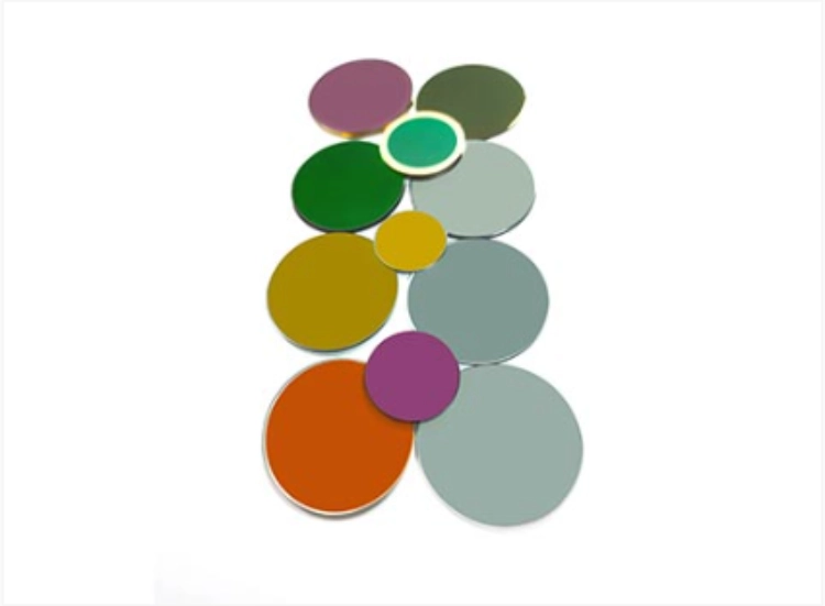
Separate In-Band Light From Out-of-Band Interference
| Lighting condition | Filter choice to evaluate | What to verify |
| Mainly visible interference | Long-pass | The cut-on clears the needed emitter output across the image. |
| Unwanted near-infrared on the long side or on both sides | Bandpass | Blocking covers the background wavelengths the detector can see. |
| Interference overlaps the emitter band | Review illumination, geometry, or capture timing | Spectral filtering alone will pass some of the interfering light. |
How to Compare Both Filters on the Same Camera
Test Contrast at the Center and Edges
Use a pair of frames for each filter. Leave the camera and its settings alone between shots. Take the first frame with the lamp off, then turn it on and save the second. On a gate camera, look at the plate and a nearby patch of background in both frames. A darker image can be a bad trade if the plate goes dark too. Run the pair again under the lighting that washed out the plate.
Use the same target in the center and near a corner. If only the corners lose the target return, check the filter’s angle response and whether the mount clips the beam. If the frame looks acceptable only after auto exposure changes, repeat with the production exposure limits and check motion detail at the required distance.
Turn the Test Into a Supplier Specification
A quote for a filter at “850 nm” leaves the supplier several ways to interpret the job. Sketch the rising edge for a long-pass and both edges for a bandpass. Put the transmission and rejection limits along the sketch where they apply. Write the test angle and temperature beside the curve so the supplier knows what the sample needs to demonstrate.
If the footprint is already frozen, send the camera and illumination requirements with the drawing. BoDian works from drawings as well as customer samples and incoming materials. Wavelength, dimensions, and film design can be set for custom work. The company uses magnetron sputtering and vacuum evaporation for coatings. Its spectral checks cover transmittance, reflectance, and absorbance.
BoDian’s test equipment includes Cary 5000 and Cary 7000 spectrometers and a PerkinElmer Spectrum 3. The optical measurements cover ultraviolet, visible, and infrared wavelengths. On the mechanical side, calipers and micrometers are used to check dimensions against tolerances. Visual inspection and microscopy can check the surface and catch chips or cracks. Put the expected optical and mechanical results on the same sample checklist.
Frequently Asked Questions
Can One Filter Serve Both 850 nm and 940 nm?
It can if the finished filter transmits enough of both LED spectra and meets the blocking requirement. A narrow bandpass centered on one source may lose much of the other source’s return. Check both overlaps with the detector curve before sharing one filter across the two designs.
Does a Narrower Passband Always Improve the Image?
The middle of the image can look fine while the target fades at the edge. When the band is narrow, a shift with incidence angle can put part of the emitter spectrum outside it. Check corner signal before buying the narrower design.
Can a Long-Pass Filter Replace the Daytime IR-Cut Filter?
The day filter has to keep near-infrared out of the color channel. A night long-pass that lets the illuminator through would let near-infrared reach that sensor. Check the day and night positions separately if the camera uses a switching filter.